
Your Cart is Empty
No need to buy OEM and pay 2x the price.
Nilfisk Advance VA75006, Pick-up tool mounting plate
FactoryCat/Tomcat 290-234A, Spare Key Set of 2 Keys
Glad I was able to purchase this item.
Free Shipping on Parts Orders Over $99
Free Shipping on Parts Orders Over $99

July 20, 2026 5 min read
SAFETY WARNING: Before inspecting harness, plugs or taking static resistance readings, set the key switch to OFF and unplug the main red battery cable. Always wear eye protection and chemical-resistant gloves when working around 24V battery systems.
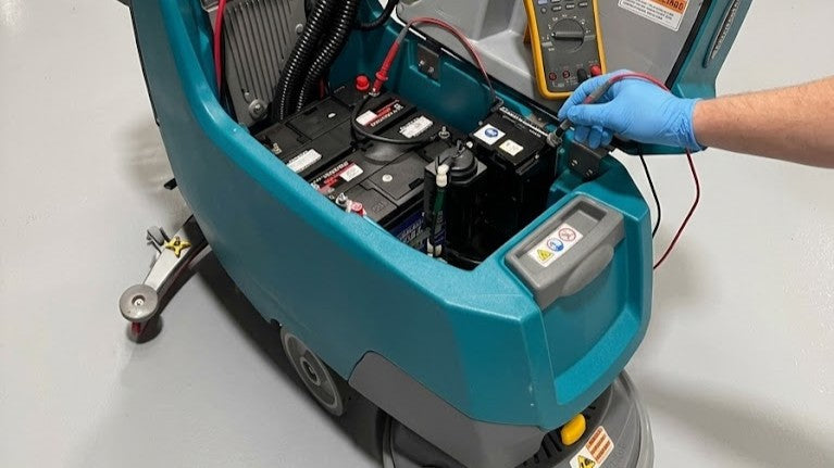
Modern commercial floor scrubbers like the Tennant T300 and T300e rely on multi-pin Molex and Deutsch connectors to route logic signals between the control console, main board, and peripheral sensors. Water, cleaning chemicals, and vibrations can quickly ruin an otherwise good electrical connection.
The Three Terminal Failures to Look For:
Understanding whether a symptom is caused by an Open Circuit or a Short to Ground saves hours of harness tracing:
+-----------------------------------------------------------------------------------------+
| FAULT TYPE | COMPONENT SYMPTOM | BREAKER STATUS | COMMON CAUSE |
+-----------------------------------------------------------------------------------------+
| Open Circuit | Will not turn ON | Remains SET | Cut wire, loose pin, |
| | | (Does not trip) | failed switch [cite: 253, 258] |
+-----------------------------------------------------------------------------------------+
| Short to Ground | Blows/Trips instantly | TRIPS immediately | Pinched cable to frame, |
| | when energized | when triggered | shorted motor |
+-----------------------------------------------------------------------------------------+
Tennant T300 / T300e Circuit Breaker Quick Map
When a breaker trips, reference this map to isolate the exact branch circuit:
The machine control board relies on physical switches and sensors to verify machine safety before outputting power.
Procedure A: Scrub Head Position Switch (SW4)
Procedure B: Squeegee Position Switch (SW8)
Procedure C: Control Handle Bail Switch Assembly
Because walk-behind scrubbers fold, pivot, and lower during operation, specific points on the main wiring harness experience severe flex fatigue:
+-------------------------------------------------------------------------------------------+
| LOCATION | FLEX CAUSE | CRITICAL WIRES TO INSPECT |
+-------------------------------------------------------------------------------------------+
| 1. Handle Neck Pivot | Adjusting console height | • Wire 6 (BLU - Switched B+) |
| | during operation | • Wire 30/31 (TAN/PNK - Bail Switch) |
| | | • Wire 33/34 (ORA/YEL - Speed Pot) [cite: 207]|
+-------------------------------------------------------------------------------------------+
| 2. Scrub Deck Linkage | Continuous head raising & | • Wire 24 (YEL) / Wire 12 (BRN - Motor) |
| & Lift Actuator | lowering cycles [cite: 22] | • Wire 28 (GRY - Head Position SW4) |
| | | • Wire 15 (GRN - Actuator Pin J4-3) [cite: 224]|
+-------------------------------------------------------------------------------------------+
| 3. Rear Frame & | Lowering/raising squeegee | • Wire 26 (BLU - Squeegee SW8) |
| Squeegee Pivot | linkage assembly [cite: 1065]| • Wire 9 (WHT) / Wire 10 (TAN - Drive) [cite: 207]|
+-------------------------------------------------------------------------------------------+
Diagnostic Tip: If an issue occurs intermittently only when turning or lowering the deck, attach your DMM to the suspected wire pin and perform a harness wiggle test while watching for continuity dropouts.
On Tennant T300 models, control modules (User Interface, Machine Control Module, ec-H2O, On-Board Charger, and i-Drive) communicate over a 2-wire Controller Area Network (CAN-Bus).
[User Interface Module]
│
CAN+/YEL │ CAN-/GRN
┌──────────┴──────────┐
│ │
[Scrub Module] [i-Drive Motor Controller]
Wire Color Identification:
CAN-Bus Resistance Test (Power OFF):
The CAN network uses two 120 Ohm terminating resistors connected in parallel at opposite ends of the system.
[Measure CAN Resistance Across YEL & GRN]
│
┌─────────────────────────┼─────────────────────────┐
Reads ~60 Ω Reads ~120 Ω Reads < 30 Ω or > 1M Ω
│ │ │
Healthy Network! One terminating Shorted CAN lines or
Both 120 Ω resistors resistor or cable damaged control module
parallel-connected [cite: 262]. branch is open [cite: 262]. transceiver chip[cite: 262, 271].
Technical Summary Checklist
Need OEM Tennant T300 Replacement Parts? Keep your equipment running at peak performance with factory-certified replacement components: Shop T300/T300e Parts
Sign up to get the latest on sales, new releases and more …
No need to buy OEM and pay 2x the price.
Nilfisk Advance VA75006, Pick-up tool mounting plate
FactoryCat/Tomcat 290-234A, Spare Key Set of 2 Keys
Glad I was able to purchase this item.
Fit perfectly and works just like OEM. Very pleased !