
Your Cart is Empty
No need to buy OEM and pay 2x the price.
Nilfisk Advance VA75006, Pick-up tool mounting plate
FactoryCat/Tomcat 290-234A, Spare Key Set of 2 Keys
Glad I was able to purchase this item.
Free Shipping on Parts Orders Over $99
Free Shipping on Parts Orders Over $99

July 20, 2026 5 min read
SAFETY WARNING:Always set the key switch to OFF and unplug the main battery cable before disconnecting control module harness plugs or servicing electrical panels. Static discharge can destroy logic chips; wear a grounded ESD wrist strap attached to battery negative when handling bare circuit boards.
The Tennant T300 and T300e communicate electrical system status through two primary operator interface styles:
Membrane/BDI Interface: Pro-Panel LCD Touchscreen:
┌─────────────────────────┐ ┌─────────────────────────┐
│ [⚡] [●] [○] [●] [○] │ │ FAULT CODE: 0x0106 │
│ Flashing LED Pattern │ ────► │ Scrub Motor Short Fault │
└─────────────────────────┘ └─────────────────────────┘
When diagnosing a machine in the field, cross-reference BDI flash sequences or Pro-Panel hex codes against the fault matrix below before condemning expensive logic boards.
Use this factory reference table to quickly identify the root cause and immediate corrective actions for common T300/T300e fault codes:
|
LCD Fault Code |
Condition |
Primary Root Cause |
Field Correction Step |
|
0x0102 |
Scrub Board Power Loss |
Blown in-line fuse; loose switched B+ power at Wire 6 (BLU) Pin J8-7. |
Inspect 70A main line fuse FU1 and harness connector J8 Pin 7. |
|
0x0106 |
Scrub Motor Short Fault |
Shorted scrub motor winding or pinched Wire 24 (YEL) / Wire 12 (BRN). |
Disconnect motor plug J10. Check winding resistance (< .2 Ohms) indicates internal motor short). |
|
0x0107 |
Scrub Motor FET Fault |
Damaged internal field-effect transistor (FET) on Machine Board or severe voltage drop during startup. |
Check power and ground connections at J6/J7. If 24V supply is clean, replace Machine Control Module. |
|
0x0501 |
Vac Motor Open Warning |
Disconnected connector J10; worn vacuum motor carbon brushes; blown 20A breaker CB6. |
Verify connector J10 is seated. Test 20A breaker CB6 and measure motor carbon brush length. |
|
0x0507 |
Vacuum FET Fault |
Failed vacuum output driver on main control board. |
Replace Machine Control Module. |
|
0x0704 |
ec-H2O CAN Comm Fault |
ec-H2O module unpowered; 4A breaker CB2 tripped; failed M2 relay. |
Check 4A CB2. Measure 24V DC at ec-H2O connector J12 Pins 11 & 12. |
|
0x0910 |
Propel Breaker Tripped |
30A CB4 tripped; i-Drive harness unplugged; transaxle motor bound or overloaded. |
Reset CB4. Check i-Drive white 14-way connector and drive wheel rotation. |
|
0xF103 |
Charger CAN Comm Fault |
On-board charger lost power or CAN network line broken. |
Power cycle machine. Perform CAN resistance check across YEL & GRN communication lines. |
To avoid replacing a good control board when a peripheral sensor or motor is at fault, follow the SUN-I/O System Isolation Procedure. SUN-I/O checks four core board states: Switched power, Unswitched power, Negative ground, and I/O (Inputs/Outputs).
[Machine Function Fails to Actuate]
│
Step 1: Check SUN Board Power Supplies
(Unswitched B+, Switched KSI, B- Ground)
│
┌──────────────┴──────────────┐
Power Missing Power Present
│ │
Check Key Switch, CB1, Step 2: Check Component
& Main Power Cables [cite: 253, 285] Inputs to Board
│
┌─────────────┴─────────────┐
Inputs Missing Inputs Present
│ │
Check Microswitches Step 3: Measure
(SW4, SW8, Bail) [cite: 294, 309] Board Output
│
┌─────────────┴─────────────┐
Output Missing Output Present
│ │
Board FET Failed Harness, Relay,
(Replace Module) or Motor Issue
Step 1: Verify Board Supply Voltage (SUN)
Step 2: Verify System Logic Inputs (I)
If power supply is confirmed, test command inputs entering the module before blaming the board:
Step 3: Measure Component Board Output (O)
Command the function and measure output voltage directly at the board output terminals:
A frequent challenge in field repair is determining whether error code 0x0106 (Scrub Motor Short) or 0x0107 (Scrub Motor FET Fault) means the motor damaged the board, or if the board failed independently.
+-----------------------------------------------------------------------------------------------+
| SYMPTOM / CODE | RESISTANCE TEST AT MOTOR PLUG | BOARD OUTPUT STATUS | REQUIRED ACTION |
+-----------------------------------------------------------------------------------------------+
| Code 0x0106 | Winding reads 0.0 Ω | Board trips | Replace scrub |
| (Motor Short) | (Shorted to frame or case) | instantly on bail | motor; repair |
| | | engagement | harness. |
+-----------------------------------------------------------------------------------------------+
| Code 0x0107 | Winding reads normal | Output stays 0V DC | Replace Machine |
| (FET Fault) | (0.8 Ω to 1.5 Ω) | even when un-plugged | Control Module |
| | | from motor | assembly. |
+-----------------------------------------------------------------------------------------------+
Tech Tip to Prevent Secondary Board Failure: Never plug a newly installed Machine Control Module into an untested scrub or vacuum motor that previously caused a short circuit code. Always verify winding resistance to ground (> 1 M Ohms) before energizing a new board!
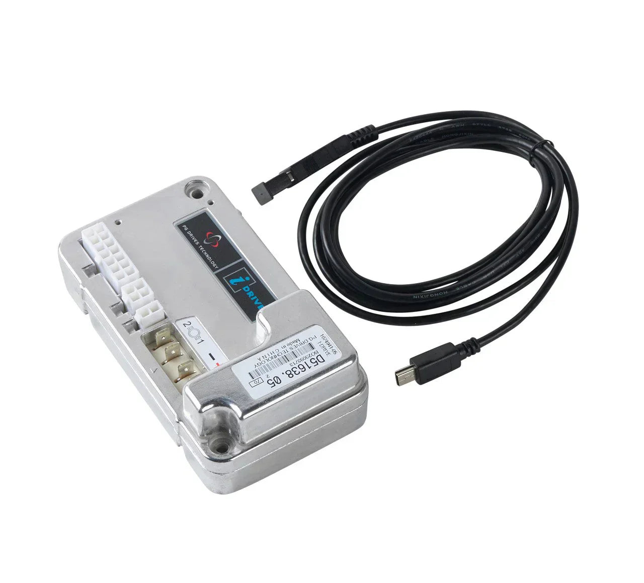
When replacing major electrical controls on the Tennant T300 series—such as the Interface Module, Machine Control Module, or i-Drive Propel Controller—the new hardware must be programmed to match the machine's specific physical options.
[PC / Service Laptop]
│
USB to Mini-USB Cable [cite: 369]
│
[Operator Console Programming Port] [cite: 369, 573]
│
┌──────────────────────┼──────────────────────┐
[Interface Module] [i-Drive Controller] [ec-H2O Module] [cite: 371, 372, 376]
Module Replacement Checklist:
Technical Summary Checklist
Need OEM Tennant T300 Replacement Parts? Keep your equipment running at peak performance with factory-certified replacement components: Shop T300/T300e Parts
Sign up to get the latest on sales, new releases and more …
No need to buy OEM and pay 2x the price.
Nilfisk Advance VA75006, Pick-up tool mounting plate
FactoryCat/Tomcat 290-234A, Spare Key Set of 2 Keys
Glad I was able to purchase this item.
Fit perfectly and works just like OEM. Very pleased !