
Your Cart is Empty
No need to buy OEM and pay 2x the price.
Nilfisk Advance VA75006, Pick-up tool mounting plate
FactoryCat/Tomcat 290-234A, Spare Key Set of 2 Keys
Glad I was able to purchase this item.
Free Shipping on Parts Orders Over $99
Free Shipping on Parts Orders Over $99

July 19, 2026 4 min read
Operating System Voltage (Battery Model):24V DC
Solenoid Valve Terminal Voltage: 21.4V - 25V DC(when handle lever is pulled)
Power Board MOS-FET Thermal Cutoff Limit:150 Celsius
Board Mounting Screw Torque:3 NM(Must apply thermal conductive paste to back plate)
Brush Motor Mounting Bolt Torque: 9 NM
Brush Head Pivot Bolt Torque:23 NM
| Component | Test Condition | Min Current | Max Current | Wear Threshold / Replacement Limit |
| 24V DC Brush Motor |
No Load (Brush Raised) |
2 A |
3.5 A |
Carbon brush length< 8 MM |
| 24V DC Brush Motor | Light Load (Empty Tank) |
7 A |
9 A |
Replace all 4 carbon brushes simultaneously |
| 24V DC Brush Motor |
Full Load (Full Tank, Standard Brush) |
9 A |
11 A |
Cutoff threshold: > 15 A for 20 sec |
| 24V DC Suction Motor |
No Load (Tank Removed) |
13 A |
17 A |
Carbon brush length< 6-8 mm |
| 24V DC Suction Motor | Overload Limit | — |
> 30 A |
Cutoff threshold: > 30 A for 20 sec |
NOTE: Internal motor thermal trip, blown individual motor fuses, or severed motor power cablesdo not display dashboard error codes.
                     DASHBOARD LED ERROR IDENTIFICATION
                                     │
    ┌───────────────────┬────────────┴───────┬───────────────────┐
    ▼                   ▼                    ▼                   ▼
2 FLASHES           2 FLASHES            4 FLASHES          FAST FLASHING
(Brush LED)         (Suction LED)        (Brush LED)        (Both LEDs)
    │                   │                    │                   │
Short Circuit /     Short Circuit /      Brush Motor         Power Board MOS-FET
Peak Current        Peak Current         Internal Thermal    Overheating
    │                   │                Protector Tripped   (>150°C)
    │                   │                    │                   │
    ├─► Check motor     ├─► Check motor      ├─► Check for       ├─► Allow 15 min
    │   wiring short.       wiring short.        motor binding.      cool-down.
    │                   │                    │                   │
    └─► Verify rotor    └─► Check fan        └─► Test continuity └─► Check current
         spins free.         rotates free.       on 4-pin purple-    draw on both
                                                 black wires.        motors.
2 Quick Flashes — Brush Motor Short Circuit Protection
Disconnect battery power.
Rotate brush manually to ensure motor is not mechanically locked/jammed.
Disconnect power harness from brush motor terminals.Check for continuity/short to frame.
Test motor directly with isolated 24V source.If motor draws excessive peak current, inspect rotor/commutatoror replace motor assembly.
2 Slow Flashes — Motor Overload
Brush Motor Limit: Exceeding 15 A for > 20 seconds
Suction Motor Limit: Exceeding 30 A for > 20 seconds
Fix Action: Check brush pad aggressiveness/friction on floor surface, inspect carbon brushes, and check for string/debris bound in the drive reduction gearbox.
4 Flashes — Brush Motor Thermal Protector Tripped
Motor thermal cutout is aNormally Closed (NC) switch operating between80 - 110 degrees Celsius.
Bench Check: Detach the 4-pin connector on the main harness and check continuity across the twopurple-black wires.
If open-circuit while motor is cool, replace the internal thermal protector.
Tree A: Machine Completely Inoperative (No Display LEDs)
Check Battery Voltage: Ensure voltage across main terminals is > 21.5V DC
Check Fuse F1: Inspect 30A Main Fuse on battery model (8AFuse F1 on corded model).
Verify Charger Lockout Relay: Disconnect battery charger bullet connectorsE1 and bridge harness connectorsE2 to bypass charger interlock relay.If control panel powers on, replace charger module.
Check Ribbon Cable: Test 10-pole flat ribbon cable for continuity pin-to-pin between function board and power board.
Tree B: Solution / Water Flow Failure
                          NO WATER AT BRUSH HEAD
                                     │
      ┌──────────────────────────────┴──────────────────────────────┐
      ▼                                                             ▼
[ SOLENOID CLICK AUDIBLE ]                             [ NO SOLENOID CLICK ]
      │                                                             │
      ├─► Clean inline solution filter (if equipped).               ├─► Verify 21.4V-25V DC across valve
      │                                                                 fast-on terminals when lever pulled.
      ├─► Flush solution dispensing cock under tank.                │
      │                                                             ├─► IF VOLTAGE PRESENT: Solenoid coil
      └─► Disassemble solenoid valve & clear diaphragm                  faulty or valve membrane seized.
          outlet hole E.                                                Replace solenoid coil/assembly.
                                                                    │
                                                                    └─► IF NO VOLTAGE: Test output from
                                                                        power board contact J3 / check 10-pole
                                                                        ribbon cable continuity.
Replacing the Power Control Card
Thermal Dissipation Safety: Clean mounting plate thoroughly.Youmust apply a fresh layer of thermally conductive silicone paste to the back of the new power card prior to mounting.
Torque Spec: Tighten all 4 board mounting boltsE to 3 NM.Do not over-torque.
Battery Charger DIP Switch Configuration (SW2)
When swapping battery chemistry, configure switchSW2 on the internal charger board:
      EXIDE GEL (Default)           DISCOVER AGM                 LEAD-ACID (WET)
        [ SW2 Board ]               [ SW2 Board ]                [ SW2 Board ]
        ┌───────────┐               ┌───────────┐                ┌───────────┐
     1  │  ■  OFF   │            1  │  ■   ON   │             1  │  ■  OFF   │
     2  │  ■  OFF   │            2  │  ■   ON   │             2  │  ■  OFF   │
        └───────────┘               └───────────┘                └───────────┘
Confirmation Verification: Upon plugging AC power into wall, observe status LED:
2 Green Flashes: Configured for Gel / AGM profile.
2 Red Flashes: Configured for Wet / Lead-Acid profile.
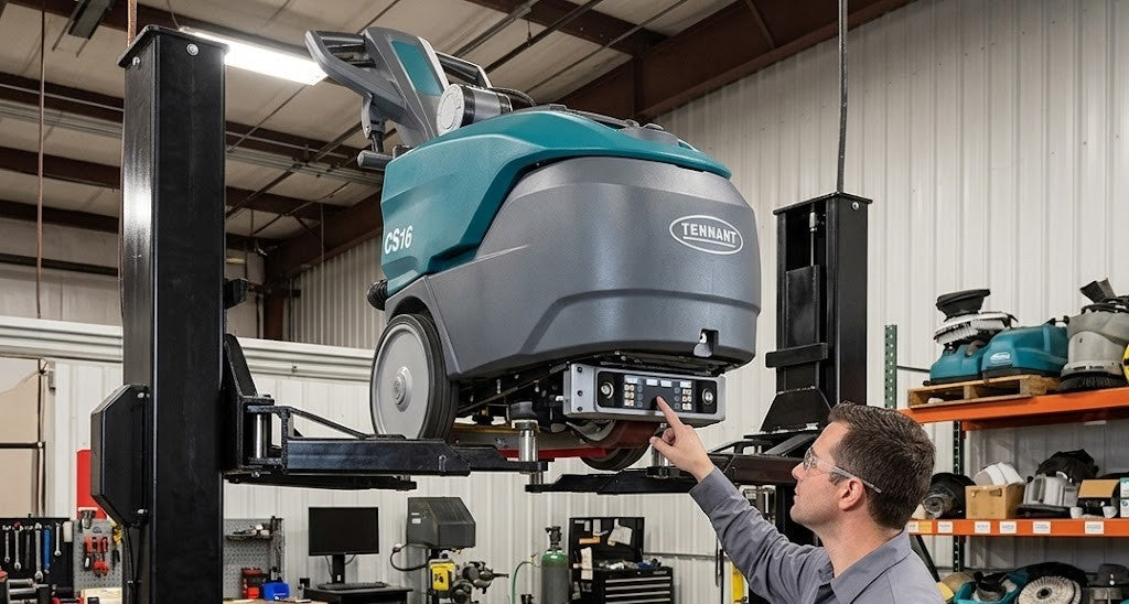
Whether you need replacement squeegee blades, brush motors, filters, or battery care supplies, keeping OEM-spec parts on hand ensures minimal downtime. Contact our service team or explore our catalog for exact-fit replacement parts for Tennant, Nobles, and other leading floor scrubber brands. Shop Tennant CS16 Parts
Sign up to get the latest on sales, new releases and more …
No need to buy OEM and pay 2x the price.
Nilfisk Advance VA75006, Pick-up tool mounting plate
FactoryCat/Tomcat 290-234A, Spare Key Set of 2 Keys
Glad I was able to purchase this item.
Fit perfectly and works just like OEM. Very pleased !